This is default featured post 1 title

Go to Blogger edit html and find these sentences.Now replace these sentences with your own descriptions.This theme is Bloggerized by Lasantha Bandara - Premiumbloggertemplates.com.

This is default featured post 2 title

Go to Blogger edit html and find these sentences.Now replace these sentences with your own descriptions.This theme is Bloggerized by Lasantha Bandara - Premiumbloggertemplates.com.

This is default featured post 3 title

Go to Blogger edit html and find these sentences.Now replace these sentences with your own descriptions.This theme is Bloggerized by Lasantha Bandara - Premiumbloggertemplates.com.

This is default featured post 4 title

Go to Blogger edit html and find these sentences.Now replace these sentences with your own descriptions.This theme is Bloggerized by Lasantha Bandara - Premiumbloggertemplates.com.

This is default featured post 5 title

Go to Blogger edit html and find these sentences.Now replace these sentences with your own descriptions.This theme is Bloggerized by Lasantha Bandara - Premiumbloggertemplates.com.

ITT :: GPRS GSM Cellular Modem

BlueTree GPRS GSM Cellular Modem with GPS

The BT-2010 GSM GPRS cell modem is designed to military (MIL) and automotive (SAE) specifications for ruggedness in harsh environments, including temperature, humidity, vibration and shock. Integrated mounting feet make it suitable for mounting in a vehicle or other harsh environments
  • BT-2010 GPRS Standard GSM Cellular Modem with GPS
  • RUGGED - RELIABLE - HIGH PERFORMANCE


  • Rugged Design
  • Dual-Band GPRS 850Mhz and 1,900Mhz
  • High-Speed Data
  • Maximum Power and Coverage
  • Standard Communications Protocols
  • Modem Management Software - BlueVue
  • Proven Reliable RF Module
  • GPS
The BT-2010 modem is designed to military (MIL) and automotive (SAE) specifications for ruggedness in harsh environments, including temperature, humidity, vibration and shock. Integrated mounting feet make it suitable for mounting in a vehicle or other harsh environments
The BT-20x0 modem supports both North American GPRS frequencies, including 850 MHz and 1,900 Mhz.
The BT-2010 supports GPRS Class 8, meaning it provides the highest  possible throughput available on GPRS networks (up to 56 kbps).
The BT-2010 modem uses a full power transceiver and high-efficiency screw-on antenna connector. Users benefit from optimum signal strength and coverage.
The BT-2010 modem supports: GPRS packet data connections CSD circuit-switched (dial-up) data connections Serial RS-232 (or optional USB adapter)
Communications protocols: AT commands and PPP
BlueVue modem management software provides a Windows™-based graphical interface that allows you to: Program the modem Monitor status of connections Initiate connections/data sessions View diagnostic info, such as signal strength, and network status GPS - display and redirection
The BT-2010 uses the RIM1902G GPRS RF module. The result is the ultimate in reliability from the industry leaders in GPRS technology.
The BT-2010 provides standard GPS. The modem incorporates an internal Trimble Lassen SQ GPS module and supports standard TSIP, TAIP and NMEA 0183 protocols. The GPS information is available on the secondary serial port.
Customers benefit from the support of our Value-Added Resellers and from the knowledge of BlueTree's development team. Our 1-year warranty is included, plus optional 3-year extended warranty for total protection.
BlueTree focuses exclusively on wireless modems for mobile and industrial applications. The BT-series modem provides all the ruggedness you need without additional features you don't.

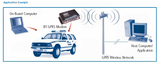
APPLICATION EXAMPLES

  • Police, Fire, EMS and other Emergency Services
  • Public Transit and Transportation
  • Vehicle Tracking - AVL
  • Field Service & Mobile
  • Dispatch
  • Utility Automatic Meter
  • Reading (AMR)
  • Automated machine-to-machine
  • (M2M)
  • Telemetry and SCADA


ITT :: Mesh Network with WiFi And WiMAX

Mesh Network with WiFi And WiMAX


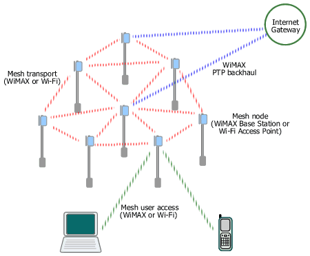
Mesh topology is not supported by existing IEEE's wireless LAN standards but it becomes popular as city-wide (municipal) Wi-Fi network deployment gains more supporters day after day. In a mesh network, each node (i.e. base station or access point) connects to several neighboring nodes and on to a mesh gateway (i.e. a base station that aggregates the mesh network traffic and routes it to the Internet). Since each node has many routes to a mesh gateway, mesh network is very reliable. But mesh network is more complex to manage and poses interference challenge especially for operation in a license-exempt band such as in Wi-Fi case.
WiMAX access, transport, and backhaul in a municipal Wi-Fi mesh network
Figure. Mesh Network with Wi-Fi and/or WiMAX
WiMAX can work on all layers of a municipal mesh network (hotzone/metro zone).
By examining current Wi-Fi mesh network architecture, basically there are three layers. These are mesh access handling user access to a mesh node, mesh transport interconnecting mesh nodes and routing traffic to mesh gateways, and backhaul connecting a mesh gateway to an Internet PoP (Point of Presence) or other content gateways.
Backhauls for mesh Wi-Fi networks are provided using various wired and wireless solutions, i.e. fiber optic, leased line, DSL, and proprietary point-to-point (PTP) or point-to-multipoint (PMP) radio including some pre-WiMAX equipment. A wireless backhaul - specifically WiMAX - enables flexible placement of a mesh gateway node anywhere in the network, therefore it doesn't have to be located in a telco's CO or close to a fiber/DSL termination point. The portable WiMAX equipment (Base Station) also allows fast installation and easy relocation. Moreover, WiMAX was designed for outstanding performance in NLOS environment, typical in metro area with many high rise buildings. WiMAX also can operate either on licensed or unlicensed band, giving more options for operator/ISP/municipality in addressing various interference conditions and users' requirements.
The mesh transport layer provides the interconnection between mesh nodes. There is a project in the IEEE to standardize Wi-Fi as an intra-mesh transport solution, but the work is still in progress. The current established Wi-Fi solution uses proprietary technology developed by each vendor which might cause interoperability issues in the future. WiMAX can naturally replace Wi-Fi in this layer, interconnecting mesh nodes using standard equipment based on the IEEE 802.16-2004 or 802.16e which includes support for optional mesh topology. Besides, WiMAX has built-in QoS support and is optimized for longer distance (WiMAX is a wireless MAN while Wi-Fi is a wireless LAN) .
For mesh access layer, at present users connect using their Wi-Fi-enabled laptops, PDAs, or smart phones. WiMAX integration into such portable/mobile devices is still in its early stage of development. However, in several months/years to come one may expect the emergence of dual-mode Wi-Fi/WiMAX devices and network adapters (NIC, PC card, PCI Express) which can connect automatically to any available network with the best signal.

ITT :: PPPOE connection on Windows 2000

Learn How To Make PPPOE Connection In Windows2000

The first step is to DOWNLOAD RASPPPoE. You can do this with your alternative backup dialup service if you don't have an alternate Internet connection. Use the "Download and install" link on the left, and you'll want to download the version marked "32-bit release for x86 machines". Once you've completed the download, unzip the file into a temporary directory (such as C:\RASPPPoE).
Click "Start" then "Settings" then "Control Panel", then browse to "Network and Dial-Up Connections"

Download Patch:
http://www.raspppoe.com/files/RASPPPOE_098B.ZIP
http://www.raspppoe.com/files/RASPPPOE_098B_3COM.ZIP


Right-click "Local Area Connection" and select "Properties".


In the properties dialogue box, click the "Install" button.


In the "Select Network Component Type" window, select "Protocol" and click the "Add" button.

 
In the "Select Network Protocol" window, click the "Have Disk" button.
In the "Install From Disk" window, either type the name of the temporary directory to which you extracted RasPPPoE, or click the "Browse" button to navigate to it, and then click the "OK" button.
A new window opens, offering the "PPP over Ethernet Protocol" for installation. Click "OK" to start installing the protocol.

 
After the "PPP over Ethernet Protocol" is installed, return to the "Local Area Connection Properties" window and click "Close" to close the window. The protocol is now fully functional, but you still need to create a dialup connection to use it.

 
Click the "Start" button on the taskbar and select "Run" to bring up the "Run" dialogue box. Type raspppoe into the box and click the "OK" button to run the dialup Connection Setup application.

 
A dialogue box appears with a combo box labelled "Query available PPP over Ethernet Services through Adapter" at the top.
Select the network adaptor to which your broadband modem is connected from the list. If the protocol is only operating on one network adapter, the box will be greyed out, as there is no choice to make. Click the "Query Available Services" button. The application will send out a query for offered services and display the result in the list view below.
Click the "Create a Dial-Up Connection" for the selected "Adapter button".

 
Shortly afterwards, a shortcut to the new dialup connection named "Connection through (adaptor name)" should show up on your desktop.

 
Rename the connection icon to iiNet ADSL Connection.

 
To start the connection to the Internet, double-click the "iiNet ADSL Connection" icon. If it's the first time you've started the connection, you'll need to fill in the following fields:
  • Username: Enter your full iiNet username, e.g. john.citizen@iinet.net.au
  • Password: Enter your password as supplied by iiNet
Click the "Dial" button to connect to the Internet.

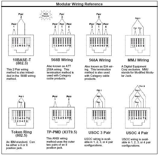
ITT :: Ethernet Cable Color Coding Diagrams


Straight-thru

Pin Color
1 white/orange
2 orange
3 white/green
4 blue (not used)
5 white/blue (not used)
6 green
7 white/brown
8 brown

Crossover
Pin Color
1 white/orange
2 orange
3 white/green
4 blue (not used)
5 white/blue (not used)
6 green
7 white/brown
8 brown
Color
white/green
green
white/orange
blue (not used)
white/blue (not used)
orange
brown
white/brown

ITT :: Types Of RJ Connectors

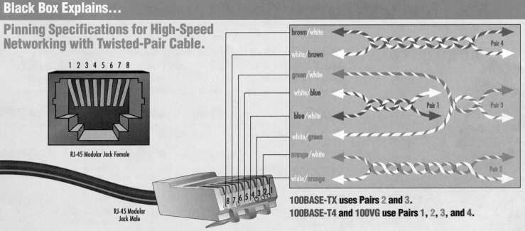
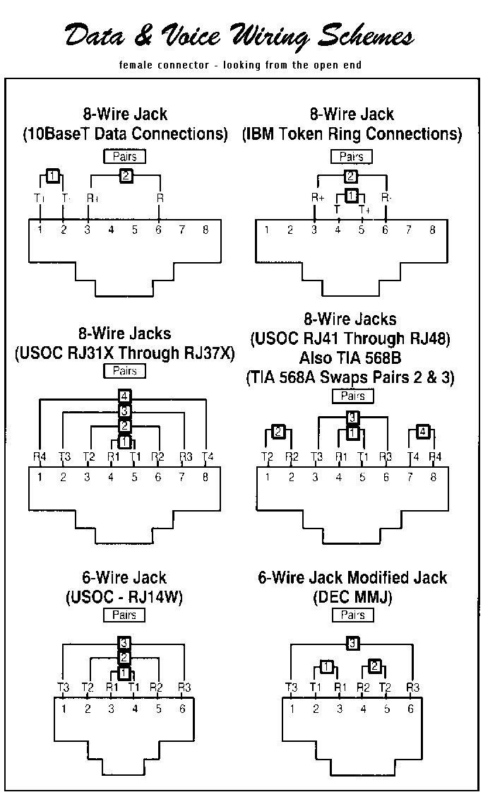
10BaseT & 100BaseT RJ Connectors

When working with 10BaseT and 100BaseT wiring, concentrators, and adapters from different vendors, it is possible to connect everything and get no communication between file servers and workstations. When there are several unknown variables, it is difficult to determine which component is broken.


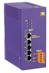
ITT :: Industrial Ethernet Switch

Industrial Ethernet Switch DC Power ANS-105

DC powered 12, 24,  VDC  Industrial rated 10/100baseT Switch
and also available in VAC power 10BaseT and 100BaseT Ethernet switch

Features
  • Complies with IEEE 802.3 10 Base-T, IEEE 802.3u 100 Base-TX, and IEEE 802.3x flow control standards
  • Provide 5 10/100 Mbps switch ports
  • Each port supports both 10/100 Mbps speed auto-negotiation and auto-sensing
  • Full/half duplex operation for each port
  • Supports 8K MAC addresses
  • Store-and-forward architecture
  • Non-blocking switching
  • Supports full-duplex flow control (IEEE 802.3x)
  • Back-pressure flow control in half duplex mode
  • Compact design with small footprint
  • DIN rail mount for industrial usage built-in
  • Power: DC 10 ~ 30 V and 115 /220VAC

The ANS – 105 provides an inexpensive flexible solution for small to medium sized applications that need DC power with a DIN rail mounting and auto-negotiation for connection speed and duplex type . It is ideal for the those industrial applications.

Specifications
  • Port Configuration: Auto-negotiation for connection speed and duplex type
  • Connector: Shielded RJ-45 Jack
  • Cables:
    • 10 Base-T (Cat.3,4,5 UTP cable, 100m max.)
    • 100 Base-T (Cat.5 UTP cable, 100m max.)
  • Filtering Address: Unicast / Multicast / Broadcast address: 8K MAC addresses per unit
  • Filtering rate: 14,880 pps for Ethernet, 148,800 pps for Fast Ethernet
  • Forwarding rate: 14,880 pps for Ethernet, 148,800 pps for Fast Ethernet
  • RAM Buffers: 2MB
  • LEDs:
    • Power status
    • 10/100, Link/Activity, Duplex/Collision status for each port
  • Environment:
    • Temperature: 0 ~ 60 C degree
    • Relative Humidity: 10% to 90% non-condensing
  • Dimension: 160 mm x 70 mm x 125 mm
  • Power: DC 10 ~ 30 V, 7W
     
  • AC power options
    24V/1A power supply (DIN-Rail mounting)

    ADN-KA52F
    24V/1.7A power supply

    DP-640
    24V/0.1 AMP


    PWR-2

ITT :: Fiber Converters


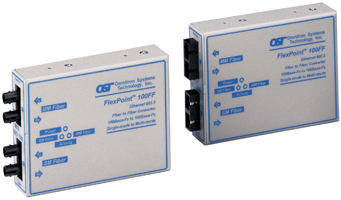
The FlexPoint 100FF Single-Mode to Multimode Fiber Converter supports Ethernet and Fast Ethernet and Token Ring.


Flexpoint 100FF


Single-Mode to Multimode or

Multimode to Single-Mode

Fiber Converters

for 100FX -100TX Fast Ethernet
FlexPoint 100FF
The FlexPoint 100FF Single-Mode to Multimode Fiber Converter supports Ethernet and Fast Ethernet and Token Ring. Capable of extending network distances up to 58 km (36 mi.) over single-mode fiber.
Available with SC and ST connectors in a variety of both multimode and single-mode fiber combinations.
Operates in half duplex or full duplex.
Supports 10Base-FL, 100Base-Fx and IEEE 802.3 specifications.
Wall-mountable or rack-mountable on a 5-unit shelf or in the 14 unit power-redundant FlexPoint Powered Chassis.
Out-of-the-box plug-and-play operation.
Software-independent.
Lifetime warranty.

The FlexPoint 100FF Single-Mode to Multimode Fiber Converter is a member of the modular FlexPoint product line. The FlexPoint product line supports the IEEE 802.3 standard and provides an extensive range of connectivity options across different media types.
The FlexPoint 100FF Single-Mode to Multimode Fiber Converter provides a cost-effective solution to extend network distances by connecting multimode fiber networks or devices over single-mode fiber cabling.
The FlexPoint 100FF provides diagnostic data through LED indicators that assist in network installation and maintenance. The LEDs report the availability of power and the detection of devices attached to the fiber ports.
The FlexPoint 100FF offers several mounting options. It can be mounted stand-alone utilizing optional wall-mounting hardware. It can also be rack-mounted using a 5-unit rack-mounting shelf or be installed in a rack-mountable, high-density, 14-unit, power-redundant chassis.

Specifications
FlexPoint 100 FF 
Connectors and Cables:
Fiber:
SC or ST
Multimode:
50/125, 62.5/125, 100/140 µm
Single-Mode:
9/125 µm
Supported Distances:

Ethernet and Token Ring:

Multimode:
5 km/16,400 ft.

Single-Mode:
20 km/66,000 ft.
Fast Ethernet:
Half-Duplex Full-Duplex
MM/Sx, 850 nm:
412 m/1,350 ft. 500 m/1,640 ft.
MM/Lx, 1300 nm:
412 m/1,350 ft. 5 km/3.1 mi.
SM/Lx, 1300 nm:
412 m/1,350 ft. 28 km/16.8 mi.
SM/Lx/LH, 1300 nm:
412 m/1,350 ft. 58 km/36 mi.
Indicators:
Power:
LED, Yellow, power applied
Fiber Link/ Receive:
LED, Green, Link/ data received
Dimensions/Weight: W:3.0"xD:4.0"xH:1.0"/ 6 oz.
Power: 9 VDC/500 mA or 5 VDC/750 mA
Physical/ Environmental:
Temperature: Operating: 0 to 70 degrees C
Storage:: -40 to 80 degrees C
Humidity:
0-90% (non-condensing)

Ordering Info
DC power the X will be 0
as in 4411-0
115VAC power the X will be 1
as in 4411-1
220VAC power the X will be 2
as in 4411-2
Model
Port 1
Port 2
Media Type
Distance
Media Type
Distance
4411-x
MM/SC/Lx 1310 nm
5 km
SM/SC/Lx 1310 nm
28 km
4412-x
MM/ST/Lx 1310 nm
5 km
SM/ST/Lx/LH 1310 nm
58 km
4413-x
MM/SC/Lx 1310 nm
5 km
SM/SC/Lx/LH 1310 nm
58 km
4410-x
MM/ST/Lx 1310 nm
5 km
SM/ST/Lx 1310 nm
28 km
4414-x
MM/ST/Sx 850 nm
500 m
SM/ST/Lx 1310 nm
28 km
4415-x
MM/SC/Sx 850 nm
500 m
SM/SC/Lx 1310 nm
28 km
4416-x
MM/ST/Sx 850 nm
500 m
SM/ST/Lx/LH 1310 nm
58 km
4417-x
MM/SC/Sx 850 nm
500 m
SM/SC/Lx/LH 1310 nm
58 km
4418-x
MM/ST/Sx 850 nm
500 m
MM/ST/Lx 1310 nm
5 km
4419-x
MM/SC/Sx 850 nm
500 m
MM/SC/Lx 1310 nm
5 km
4420-x
MM/ST 1310 nm
5 km
MM/ST 1310 nm
5 km
4421-x
MM/SC 1310 nm
5 km
MM/SC 1310 nm

ITT :: Nokia Battery Identification


Identification Step 1


Identification Step 2


Identification Step 3


Identification Step 4


WEBSITE LINK :

http://batteryreplacement.nokia.com/batteryreplacement/en/

ITT :: Blog Website Making


Blog Web Step 1


Blog Web Step 2


Blog Web Step 3


Blog Web Step 4


ITT :: How to disable Delete Confirmation Dialog Box

Today tip is very useful particularly for those users who want to restrict the common users to shutdown public computer in common areas.  You can disable the "Turn off Computer" button on the start menu and a common user will not "Turn Off, Restart and Stand By" a computer. Using registry editor, you can implement this task in all windows XP versions with minimum effort
Follow the given steps to disable Turn off Computer" button on the start menu:
To use this feature, you will need to be logged into your computer with administrative rights.
Click Start button and type regedit in Run option then press Enter for next.


Here locate the location to:

HKEY_CURRENT_USER\Software\Microsoft\Windows\CurrentVersion\Policies\Explorer 

Here in right side panel, right click to create a new DWORD value with the name NoClose. 
 
Now assign number 1 in value data box and close the registry editor.
 
 
Now close the registry editor and restart your computer after any changes to go into effect.
But next time, if you want to enable "Turn Off Computer" button on start menu then simply change the value of data box to 0 or delete NoClose DWORD item

ITT :: Disable the Security Center warnings

Disable the Security Center warnings
Security is a system of safeguards designed to protect a computer system and important data from damage or access by unauthorized persons. Different antivirus and firewall programs are used to manage the security of the computer. Some time this is build-in antivirus or firewall program in windows XP to maintain the computer security. But if your windows is not provided with any antivirus, firewall program and Automatic Updates, your windows security center will alerts you a message "Your computer may be at risk. Your virus protection status is unknown" with useless repeating reminder. You can disable this message permanently by changing the values of “AntiVirusDisableNotify” in windows registry.

Follow the given steps to edit the computer registry for disable message:
  • First click on Start button then type Regedit in Run option.
  • Here locate the location to:

·         HKEY_LOCAL_MACHINE\SOFTWARE\Microsoft\Security Center

  • Here in right side panel, double click on AntiVirusDisableNotify and set its value 1.
  • Now close the registry editor and restart your computer after any changes to go into effect.

ITT :: Remote Desktop For Computer Having Dynamic ip

Remote Desktop For Computer Having Dynamic IP

1. Using hamachi:-

Introduction
:-
The Reason which stop you from connecting to remote computer using dynamic ip is that your isp provide you two ip one which is inside the Lan and other outside the lan this is that ip which change every time you On your computer or restart connection( so because of that conflict you can do remote connection with computer). so one way of doing remote connection would be by joining same lan(then we don't need to go outside the lan) and then connecting to the computer. therefore for this we use hamachi(software) which you can download from here  http://www.ziddu.com/download/8296376/hamachi.msi.html.

Steps:-
1. As soon as downloading gets over install it into your computer in the process of installing it will ask you for
a) Your name
b) Network to join(you can create a network)
c) password of network(give password for that network)
here you can consider network as one lan and to join any network you must know password because you want to connect to your friends computer so tell your friend to join the network that you have created.
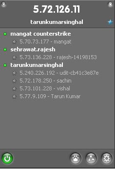
2. once hamachi is installed look at system tray you will found here a three green dots in traingular form (appeared) click on it.
3. then you will get a window as shown.

the ip shown on the above part of this window is your ip address and similarly your friend will get different one. after you both join the group you both will be listed into your network. hence now you can use these ip address for remote connection.
NOTE:- you can use my network
network: tarunkumarsinghal


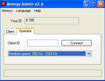
2. Using Ammyy Admin
Introduction:-
other way of remote connection is using other software.
there are so many software on the web that can be used for remote connection. but most of them are so complecated that we first have to read about them on net before we use it. so to sovle this problem i have found one software which is very easy to use and operate. named ammy admin it is a free software.

Steps to use it for remote connection are as follow:-
1. downoad it from here   http://www.ziddu.com/download/8296362/AMMYY_Admin.exe.html.
2. start by double clicking.
3. a window will open ask your friend for it your id and write it into your windows box and click connect and that' it.
4. Now enjoy remote connection.

ITT :: Shutdown Trick

 Shutdown Trick

15 Imidiate rapid shut down window
while shutting down window. open task manager(Ctr+Alt+Del),
Select shut down tab. and press ' Ctrl ' key while select Turn Off from dis tab.
Count 5 4 3 2 1 Voila!!! U r window will rapidly shut down.


Speed Up Ur Shut down !!

Start Regedit.
Navigate to HKEY_LOCAL_MACHINE/SYSTEM/CurrentControlSet/Control.
Click on the "Control" Folder.
Select "WaitToKillServiceTimeout"
Right click on it and select Modify.
Set it a value lower than 2000 (Mine is set to 200)
.

and !

Like previous versions of windows, it takes long time to restart or shutdown windows xp when the "Exit Windows" sound is enabled. to solve this problem you
must disable this useless sound. click start button then go to settings -> control panel -> Sound,Speech and Audio devices -> Sounds and Audio Devices -> Sounds, then under program events and windows menu click on "Exit Windows" sub-menu and highlight it.now from sounds you can select,choose "none" and then click apply and ok. now you can see some improvements when shutting down your system.

ITT :: Telenor Free GPRS Settings Only For Pakistan


ACCES POINT : mms
IP ADDRESS : 212.166.64.10
PROXY : 3128


hey......!!! dear now TELENOR INTERNET IS FREE WORKING 100%

SET: THESE SETTING ON YOUR MOBILE AND USE FREE INTERNET IN PAKISTAN...

ITT :: Secure Wireless Network From Hackers


The reason we secure a wireless network is to stop people from using the services of our network who don't have permission to utilize them. It is harder to secure a wireless network from hackers as compared to a classic wired network. This is due to the fact that a wireless network can be accessed anywhere inside the range of its antenna.
In order to secure a wireless network from hackers, we should take proper steps to save ourselves against security issues. If you don't secure a wireless network from hackers, you might end up without its service. The consequence might also include the utilization of our network to attack further networks. To secure a wireless network from hackers, you should follow these simple wireless networking tips:
1.       Strategic antenna placement:
The first thing you have to do is to position the access point's antenna in a place which restricts the range of its signal to go further than the required area. You should not put the antenna close to a window because glass can't obstruct its signals. Place it in a central location of the building.

Use WEP:
WEP stands for Wireless encryption protocol.  It's a customary technique for encrypting traffic on a wireless network. You should never skip it as that will allow hackers to get instant access to the traffic over a wireless network.
3.       Change the SSID, disable the broadcast of SSID:
SSID stands for service set identifier.  It is the recognition thread utilized by the wireless access point due to which the customers are capable of starting connections. For every wireless access point arranged, select an exclusive as well as unique SSID. Also, if it's attainable, hold back the broadcast of the SSID out over the antenna. It won\t appear in the listing of offered networks, while being able to provide services as usual.
4.       Disable DHCP:
By doing this, the hackers will have to decode the TCP/IP parameters, subnet mask as well as the IP address in order to hack your wireless network.
5.       Disable or modify SNMP settings:
Change the private as well as public community settings of SNMP. You can also just disable it. Otherwise the hackers will be able to utilize SNMP to get significant info regarding your wireless network.
6.       Utilize access lists:
For additional security of your wireless network, and if your access point support this feature, employ an access list. An access list lets us determine precisely which machinery is permitted to attach to an access point. The access points which include the access list can employ trivial file transfer protocol (TFTP) now and then in order to download modernized lists to steer clear of hackers.

ITT :: Cisco VPN concentrator through ISA Server 2000

Learn How to Enable a Cisco IPSec VPN client To Connect To A Cisco VPN Concentrator Through ISA Server 2000


Provide Support for the Cisco VPN Client

In most cases, IPSec VPN traffic does not pass through ISA Server 2000. However, Cisco Concentrator 3300, with the latest firmware updates, uses "transparent tunneling" that uses User Datagram Protocol (UDP) ports 500, 4500, and 10000 to communicate securely between VPN clients and concentrators.

To provide support for this configuration, create the following protocol definitions:

Note The client computer must be configured as a SecureNat client.
Port number: 500
Protocol type: UDP
Direction: Send Receive

Port number: 4500
Protocol type: UDP
Direction: Send Receive

Port number: 10000
Protocol type: UDP
Direction: Send Recieve


By creating these protocol definitions, you enable the SecureNat client to connect to the Cisco VPN server through ISA Server as all traffic is passed as UDP traffic. According to the Cisco Transparent tunneling technology, this traffic can traverse Network Address Translation (NAT) firewalls.

Note You must make sure that your Access Policy permits these three custom protocols.

Create the Protocol Definitions

Create the new custom protocols to enable the transparent tunneling feature. To do so, follow these steps:
  1. Start the ISA Management snap-in. To do so, click Start, point to Programs, point to Microsoft ISA Server, and then click ISA Management.
  2. Under Policy Elements, locate the Protocol Definitions container.
  3. Right-click Protocol Definitions, point to New, and then click Definition.
  4. In the Protocol definition name box, type a descriptive name for the definition (for example, type Port 500 UDP Send Receive), and then click Next.
  5. In the Port number box, type 500. In the Protocol type list, click UDP. In the Direction list, click Send Receive (do not click Receive Send), and then click Next.
  6. Under Do you want to use Secondary connections?, click No, and then click Next.
  7. Confirm your settings, and then click Finish.
  8. In the left pane, right-click Protocol Definitions, point to New, and then click Definition.
  9. In the Protocol definition name box, type a descriptive name for the definition (for example, type Port 4500 UDP Send Receive), and then click Next.
  10. In the Port number box, type 4500. In the Protocol type list, click UDP. In the Direction list, click Send Receive (do not click Receive Send), and then click Next.
  11. Under Do you want to use Secondary connections?, click No, and then click Next.
  12. Confirm your settings, and then click Finish.
  13. Repeat the steps above to create the protocol using a value of 10000 in steps 9 and 10.
The new custom protocols are listed in the right pane under Available Protocols.

Create a Protocol Rule

Create a protocol rule to allow access using the new custom protocols that you created. To do so, follow these steps:
  1. Start the ISA Management snap-in. To do this, click Start, point to Programs, point to Microsoft ISA Server, and then click ISA Management.
  2. Under Access Policy, locate to the Protocol Rules container.
  3. Right-click Protocol Rules, point to New, and then click Rule.
  4. In the Protocol rule name box, type a name for the rule (for example, type Allow Cisco IPSec VPN Client), and then click Next.
  5. Click Allow, and then click Next.
  6. In the Apply this rule to list, click Selected protocols.
  7. In the Protocols list, click to select the check boxes that correspond to the three custom protocols that you created earlier, and then click Next.
  8. In the Use this schedule list, click the schedule that you want to use when allowing these protocols (for example, click Work hours), and then click Next.
  9. Under Apply the rule to requests from, click Any request (unless you want to restrict these protocols to certain client address sets), and then click Next.
  10. Confirm the configuration selections, and then click Finish.
The new protocol rule is listed under Available Protocol Rules in the right pane.

Note After you perform the steps to add UDP Port 10000 as a protocol definition, you may also have to add UDP port 20000 to be able to work with some of the newer Cisco VPN Concentrators.

Note This article is designed for SecureNAT clients. You must remove the ISA Firewall client software.


ITT :: ISA 2000 VPN Server To Support Outbound L2TP IPSec


L2TP IPsec Connections Support Step 1


L2TP IPsec Connections Support Step 2


L2TP IPsec Connections Support Step 3


L2TP IPsec Connections Support Step 4


L2TP IPsec Connections Support Step 5


L2TP IPsec Connections Support Step 6


L2TP IPsec Connections Support Step 7


L2TP IPsec Connections Support Step 8


L2TP IPsec Connections Support Step 9


L2TP IPsec Connections Support Step 10


L2TP IPsec Connections Support Step 11


L2TP IPsec Connections Support Step 12


L2TP IPsec Connections Support Step 13


L2TP IPsec Connections Support Step 14


L2TP IPsec Connections Support Step 15


L2TP IPsec Connections Support Step 16


L2TP IPsec Connections Support Step 17


L2TP IPsec Connections Support Step 18


L2TP IPsec Connections Support Step 19


L2TP IPsec Connections Support Step 20


L2TP IPsec Connections Support Step 21


L2TP IPsec Connections Support Step 22


L2TP IPsec Connections Support Step 23


Share

Twitter Delicious Facebook Digg Stumbleupon Favorites More